A Spatial Light Modulator (SLM) is a device that imposes a spatially varying modulation on a light beam, altering its amplitude, phase, or polarization state pixel by pixel. The modulation pattern is programmable via a computer interface, enabling dynamic control of the optical wavefront. The most common commercial variants are electrically addressed SLMs (EASLMs), with two mainstream technologies: liquid crystal on silicon (LCOS) and digital micromirror devices (DMD)[1].
The SLM exists because fixed optical elements have fixed functions: a lens only focuses, a mirror only reflects, a prism only disperses. To generate arbitrary beam profiles, correct arbitrary aberrations, or display arbitrary holograms, you need a programmable optical element. The SLM is that element: a writable diffractive optical element (DOE)[1].
The answer: the SLM’s function is to convert a digital pattern into an optical wavefront. Its main applications are laser beam shaping, adaptive optics, holographic display, optical tweezers, pulse shaping, and optical computing[1].
1. The problem: the limits of fixed optics
A fixed optical element’s function is set at manufacture; changing the function means swapping hardware. Three classes of requirements fixed elements cannot meet:
- Arbitrary beam shaping: material processing needs flat-top beams, research needs Bessel beams or Laguerre-Gaussian (LG) vortex beams, and the beam profile changes with the task[1].
- Real-time aberration correction: atmospheric turbulence, ocular aberrations, and sample-induced aberrations change over time, and the correction must be updated in real time[1].
- Dynamic holograms: holographic display and optical computing need the diffraction pattern to change with the content[1].
The SLM solves all three classes with the same hardware: write a different pattern, get a different optical function[1].
2. The structure: LCOS and DMD
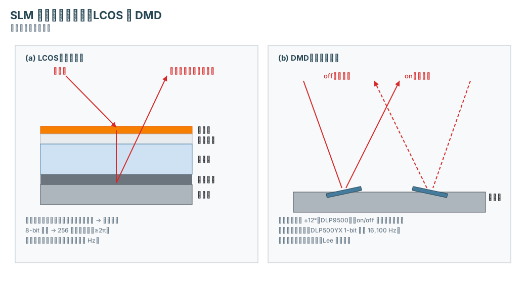
Figure 1: Cross-sections of the two mainstream SLM technologies (schematic, not to scale). Left: LCOS is a reflective structure; the light passes through the liquid crystal layer twice. Right: the DMD is an array of tilting micromirrors; each mirror steers the light on (into the optical path) or off (out of it).
The two mainstream technologies:
- LCOS (Liquid Crystal on Silicon): a reflective structure. The silicon backplane carries a mirror and pixel electrodes, with a liquid crystal layer on top. The voltage changes the liquid crystal orientation, changing the phase retardation of linearly polarized light. 8-bit grayscale gives 256 phase levels. Advantages: high resolution and high light efficiency — it redirects light rather than absorbing it. Speed is limited by liquid crystal viscosity, typically tens to hundreds of hertz[1].
- DMD (Digital Micromirror Device): an array of tilting micromirrors. Each mirror tilts ±12° (TI DLP9500), steering the light into the optical path (on) or out of it (off). It is binary amplitude modulation, with speeds in the kilohertz range (the DLP500YX reaches 1-bit pattern rates up to 16,100 Hz). Phase modulation is possible but indirect (Lee holography)[1][4][5].
There are also transmissive liquid crystal SLMs (similar to LCD displays) and ferroelectric liquid crystal SLMs (faster response)[1][2].
Spec comparison (typical commercial products):
| Parameter | Holoeye PLUTO-2.1 (LCOS) | TI DLP9500 (DMD) |
|---|---|---|
| Modulation type | Phase only (8-bit, ≥2π) | Binary amplitude (±12° tilt) |
| Resolution | 1920×1080 | 1920×1080 |
| Pixel pitch | 8.0 µm | 10.8 µm |
| Fill factor | 93% | not given in sources |
| Frame rate | 60 Hz (input) | kilohertz range |
| Interface | HDMI | not given in sources |
| Wavelength range | 420–1400 nm (by version) | 400–700 nm (visible) |
The PLUTO-2.1 is offered in several wavelength versions: VIS-014 (420–650 nm, average reflectivity 65%), NIR-145 (420–1064 nm, 80%), NIRO-024 (1064–1400 nm, 82%); all versions provide at least 2π phase retardation[2][3]. The PLUTO-2.1 is driven via HDMI, using the green channel of the video signal for 8-bit gray-level addressing; it can be driven as an extended display from a standard graphics card, and Holoeye provides an SDK[2]. Holoeye’s LETO-3 has a 6.4 µm pixel pitch (0.55-inch) and a 180 Hz input frame rate in color-field-sequential mode[3].
3. The principle: how it modulates light and shapes beams
Phase modulation (LCOS): liquid crystal is birefringent. The voltage changes the molecular orientation, changing the effective refractive index seen by the light, changing the phase. 8-bit addressing gives 256 gray levels, covering at least 2π of phase[2][3].
Beam shaping: the SLM writes a phase pattern φ(x, y) onto the beam, and a lens performs a Fourier transform — the far-field intensity distribution is the squared modulus of the Fourier transform of the phase pattern. Writing a spiral phase (phase increasing linearly with azimuth) produces a vortex beam with a phase singularity at the center (LG mode) (standard Fourier optics).
Adaptive optics: measure the wavefront aberration, write the conjugate phase (the negative of the aberration phase), and the aberration is canceled[1].
Holography: write a computer-generated hologram (CGH); the diffracted light forms an arbitrary image[1].
DMD: binary on/off, high speed, suitable for dynamic masking, projection, and high-speed beam switching[1].
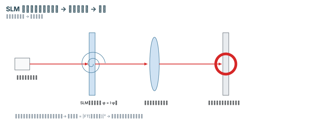
Figure 2: SLM beam shaping (schematic). The SLM writes a spiral phase, the lens performs a Fourier transform, and the far field is a vortex beam (intensity ring).
4. Limitations
- Speed: the LCOS input frame rate is 60 Hz, and the actual response time depends on the liquid crystal material version; the DMD is in the kilohertz range but binary[2][5].
- Efficiency: the LCOS average reflectivity is 65–82% (by version); amplitude SLMs work by absorbing or blocking light, with loss[1][3].
- Pixelation: the finite pixel count and fill factor (93%) produce diffraction artifacts — zero-order light and ghost orders[2].
- Wavelength: each version is optimized for a specific wavelength range; changing wavelength requires re-calibrating the phase (gamma control)[2].
- Power: high-power applications need high-reflectivity versions (dielectric mirror)[2].
5. The answer: functions summarized
| Function | Principle | Typical applications[1] |
|---|---|---|
| Beam shaping | phase pattern + Fourier transform | flat-top, Bessel, LG beams (material processing, research) |
| Adaptive optics | conjugate phase correction | microscopy, retinal imaging, free-space optical communications |
| Holographic display | CGH diffraction | 3D display |
| Optical tweezers | multiple foci | particle manipulation |
| Pulse shaping | spectral phase modulation | ultrashort pulse control |
| Optical computing | optical Fourier transform / correlation | optical computing |
Common misconceptions
- “An SLM is a display”: wrong. It is a programmable optical element; the “image” it displays is a phase/amplitude pattern for modulating light, not something for human viewing[1].
- “A phase SLM and an amplitude SLM are the same”: wrong. The phase type redirects light (high efficiency); the amplitude type absorbs or blocks light (with loss)[1].
- “A DMD can only do amplitude modulation”: not entirely. Phase modulation is possible but indirect (Lee holography)[1].
Self-check for readers
- What are the two mainstream SLM technologies, and what is each suited for?
- Why does a phase SLM have higher light efficiency than an amplitude SLM?
- How does an SLM generate a vortex beam?
Back to the opening question: what is an SLM, and what does it do? It is a programmable optical element that imposes a spatially varying modulation on a beam pixel by pixel, and its function is to convert a digital pattern into an optical wavefront — beam shaping, aberration correction, holographic display, optical tweezers, pulse shaping, and optical computing.
Applicable conditions and limits: this article takes the two mainstream commercial technologies, LCOS and DMD, as examples, and the numbers come from the Holoeye PLUTO-2.1 and TI DMD product specifications. The response times of specific liquid crystal materials, the optical details of DMD corner illumination, and the design of pulse shaping systems are not covered by the sources cited here.